Many nuclear power plants across the Europe are approaching the end of their design durability. It brings along difficulties based on high costs of decommissioning and replacement of the existing plants. Prolongation of serviceability is therefore welcome because it is significantly cheaper. On the other hand, detailed analyses of reactor vessels have to be performed because nuclear equipments are in the centre of public attention and there are severe requirements on them.
Complex analysis of existing reactor vessels contains mechanical and transport parts which are coupled together. Several analyses are necessary for estimation of vessel behaviour after more than 30 years of service life. During this long period, the vessel underwent through many stages which have to be modelled.
This article deals with hygro-thermo-mechanical and limit mechanical analyses of reactor vessel from prestressed concrete with inner steel liner. The reactor vessel is located in Hinkley, the UK.
The base analysis is coupled hygro-thermo-mechanical analysis of all service life of the reactor vessel. There is heat and moisture transfer together with creep analysis which represents the mechanical part. The creep is influenced by actual moisture and temperature. Irreversible strains and relaxed stresses are necessary for further computations.
In addition to the hygro-thermo-mechanical analysis, limit mechanical analysis is also performed at selected times. The limit analysis starts from stage obtained from the creep analysis and is based on damage models. Maximum inner pressure and distribution of damage during pressurisation are required results of the limit analysis.
Many stages of the reactor vessel are described by several load cases which can be split into mechanical and transfer load cases. The mechanical load cases contain the gravity load, prestressing caused by tendons and internal pressurization. The heat and moisture transfer are governed by several warming and cooling cycles.
The hygro-thermo-mechanical analysis has to describe whole service life of the reactor vessel, i.e. a period longer than 30 years. Different time scales are necessary in mechanical and transfer approaches. The creep analysis should use time step in days during application of prestress or during pressurization or de-pressurization and in the vicinity of these stages. Significantly longer time steps may be used elsewhere. The heat and moisture transfer requires time steps in hours during warming or cooling and in the vicinity. Longer time steps may be used if transient character changes to nearly stationary one. Unfortunately, mechanical and transfer events are not coordinated and therefore short time step has to be used for nearly whole modelled period.
All analyses cover period of more than 30 years. Time step in the computations must be set up with respect to gradients of many variables like stress, temperature etc. The time step must be approximately 2 hours during intensive heating up of the vessel and 1 day at other parts of solved period. Therefore nearly 13,000 time iterations must be performed in each analysis. Other difficulty connected with the mentioned analyses represents highly nonlinear feature of the solved problem. The Newton-Raphson method is used for linearization of the problem and several steps have to be performed during each time step in order to reach an equilibrium.
Summarized facts in the previous paragraphs lead to conclusion that really strong computational power should be used. Parallel processing and domain decomposition concept of non-overlapping subdomains form very suitable tool for overcoming of mentioned difficulties. The matrices used in analysis are generally not symmetric and therefore the Schur complement method is assumed and reduced (coarse) problem should be solved by direct method (LU factorization) or by iterative method (bi-conjugate gradient method, GMRES).
This article is organized as follows. Section 2 summarizes formulation of hygro-thermo-mechanical analysis and solution strategy for nonlinear system of algebraic equations is indicated. Section 3 describes the Schur complement method which is used for parallelization of the problem. 4 Section 5 describes analysed vessel as well as performed analyses. Several results are depicted in figures.
Coupled hygro-thermo-mechanical analysis is shortly summarized in this section. Introduction to coupled analyses can be found in reference [6]. Application of general theory to problems solved in this article was described in reference [5].
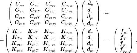
There are many possibilities of unknown selection in coupled problems. Estimation of properties of presstressed concrete used in reactor vessel was based on the following set of unknowns: displacements, pore pressures and temperature. Subscript u denotes the displacements, subscripts p1 and p2 denotes the pore pressures and subscript T denotes the temperature. Conservation equations after space discretization have the form
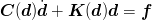
Equation (1) represents system of nonlinear ordinary differential equations, where K denotes the stiffness or conductivity matrices, C denotes the capacity matrices and f denotes the prescribed nodal forces or prescribed nodal fluxes. The matrices K and C generally depend on nodal values and this dependency results in nonlinear feature of the system. The system of differential eqiations (1) can be written compactlySolution of the system of equations (1) cannot be obtained explicitly thanks to nonlinearity and has to be found by suitable numerical method. Time discretization is defined by relationships
where d denotes the nodal values and v denotes the first derivatives of nodal values with respect to time. Subscript n denotes the time step.Substitution of expressions defined in equations (1) and (2) to the system of differential equations (1) leads to relationship
System of algebraic equations (3) is nonlinear and the Newton-Raphson method [1, 2] has to be used within every time step.Trial solution vn+1,0 of the system of equations (3) is used for computation of trial nodal values dn+1,0. Substitution of trial solution back to the system of equations (3) with modified matrices does not generally lead to equilibrium. Residuum is computed from relationship


It has to be noted that permanent recalculation of matrices K and C with respect to actual nodal values is very computationally demanding. Furthermore, matrix of the system of equation C(d) + ΔtαK(d) has to be factorized during every iteration in every time step. Speedup of described computation is therefore very desirable. In this analysis, the speedup was based on parallelization of the problem.
Application of parallel computer to numerical analysis based on solution of system of algebraic equations requires some changes in comparison with the classical single processor (sequential) computation. Domain decomposition methods create suitable framework for efficient parallel computations. Only the Schur complement method, sometimes called also method of substructuring, is used in this article and its main features are described in this section. For more details about domain decomposition methods see references [3, 4, 7, 8, 9]
The Schur complement method is discussed in connection with the finite element method. Let domain (structure) be discretized by finite elements. System of algebraic equation can be written in the form
 | (6) |
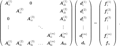
Consider decomposition of generated mesh into m submeshes. Special ordering of unknows (see references [4, 8]) leads to rearranged system of algebraic equations in the special form
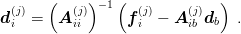
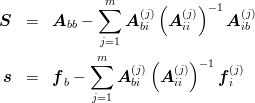
where subscript i denotes inner quantity and subscript b denotes quantity defined on boundary between two subdomains. Superscript denotes the number of subdomain. All subvectors di(j) except the last subvector d b may be expressed in the form Substitution of expressions from equation (7) to the last equation of system (7) gives
Implementation of the Schur complement method used in reactor vessel analysis was based on combination of direct and iterative methods. Inverse matrices in relationship (7) were not computed explicitly because the LDLT factorization was used. Factorizations of matrices Aii(j) can be done simultaneously. The coarse problem (7) was solved by iterative method (bi-conjugate gradient method) and therefore the matrix S was not assembled on the master processor.
The Schur complement method was applied to the system of algebraic equations (3).
Therefore, the matrix A used in equation (6) has the form C(d) + ΔtαK(d) and the vector
f from equation (6) has the form fn+1 −K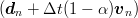 .
.
Hygro-thermo-mechanical analysis describes behaviour of vessel during its life period. Real vessel conditions were used and all relevant quantities were computed. Limit state mechanical analysis serves for estimation of design failures of the vessel. Therefore, all important quantities were saved at selected times and these quantities served as initial conditions for limit analysis of the vessel. In case of the limit analysis, all quantities were fixed on attained values and only inner pressure was growing up to the vessel destruction. Level of pressure at vessel destruction is required parameter which is important for future decision about prolongation of nuclear power plant.
The limit state mechanical analysis was based on damage material model. Scalar isotropic damage model with influence of temperature was used. System of nonlinear algebraic equations was solved by the arc-length method [2].
As was mentioned in introduction, complex analyses of existing nuclear vessels become important in connection with intended prolongation of serviceability of nuclear power plants. Described analyses were conducted within MAECENAS project supported by EU. Real reactor vessel of existing nuclear power plant located in Great Britain was analysed. All necessary informations about the vessel (geometry, lenghts, thicknesses, forces, pressures, temperatures, material properties, etc.) were obtained from British Energy company.
In order to estimate behaviour and actual stage of the vessel after more than 30 years of service, coupled hygro-thermo-mechanical analyses and limit state mechanical analyses were performed. The coupled analyses were computed first and several stages at selected times were stored. The limit state analyses of saved stages from the coupled analyses were performed later.
The reactor vessel has cylindrical shape and it is made from prestressed concrete with inner steel liner. Diameter of the cylinder is approximately 30 meters and the height is approximately 36 meters. Thicknesses of walls are about 5 meters.
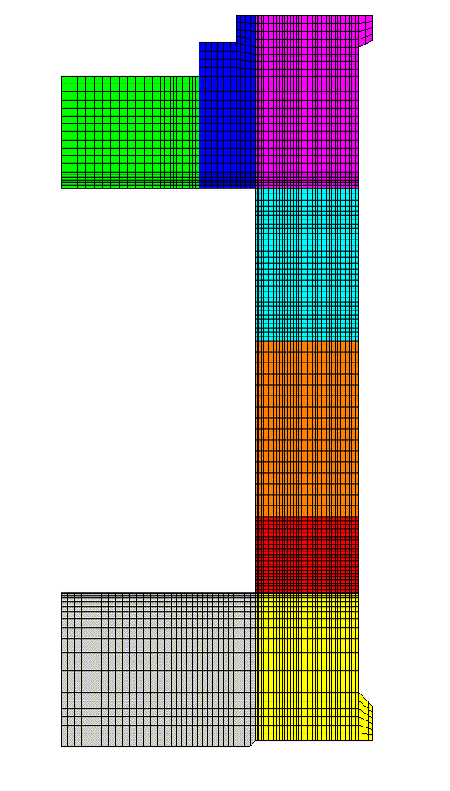
The coupled hygro-thermo-mechanical analysis consists of concurent moisture trnasfer, heat transfer and creep analysis. Therefore, there are two pore pressures, temperature and two or three displacements (it depends whether 2D or 3D model is used) defined at every node. Five or six variables at every node lead to extremely large systems of algebraic equations with relatively dense matrices. With respect to the mentioned extreme computational demands of the coupled analyses, an axisymmetric twodimensional model was used. Cross section of the vessel is depicted in Figure 1.
Whole period of service of the reactor vessel had to be modelled. Combinations of several effects led to small time which was one day and during significant heating or cooling the time step had to be reduced to one hour. Therefore more than 12,500 time steps were necessary for computation.
In order to speed computation up, parallel algorithms were used. Namely, the Schur complement method (one type of domain decomposition methods) was applied and computation was executed on cluster of eigth PC. The number of processors was established as minimum number of processors available by all teams associated in the MAECENAS project. Finite element mesh was therefore decomposed into eight submeshes and one example of such decomposition is depicted in Figure 1.
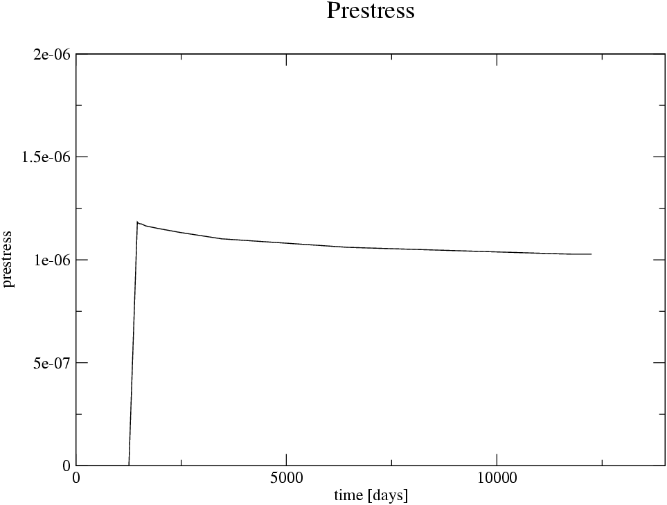
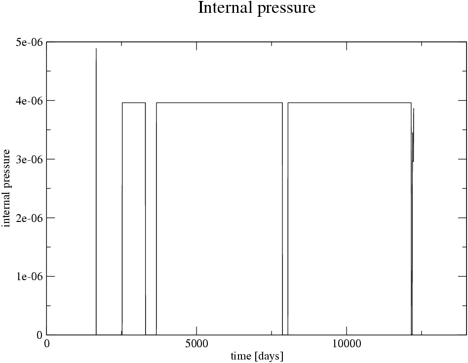
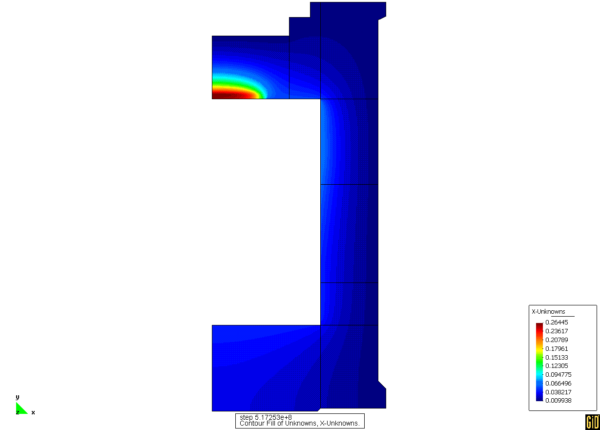
There were two groups of effects, which had to be modelled. The first group contains mechanical effects and second group contains heat and moisture transfer effects. Prestress of the vessel is important load case influencing especially creep of the structure. History of prestress is depicted in Figure 5. Prestress tendons are in the vertical as well as in the horizontal directions and they were modelled as nodal forces multiplied by time function from Figure 5. Gravity load was applied gradually during first 150 days. The last mechanical load case was internal pressure which history is depicted in Figure 3.
Heat and transfer effects were modelled by prescribed temperature and moisture.
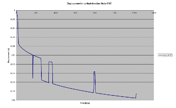
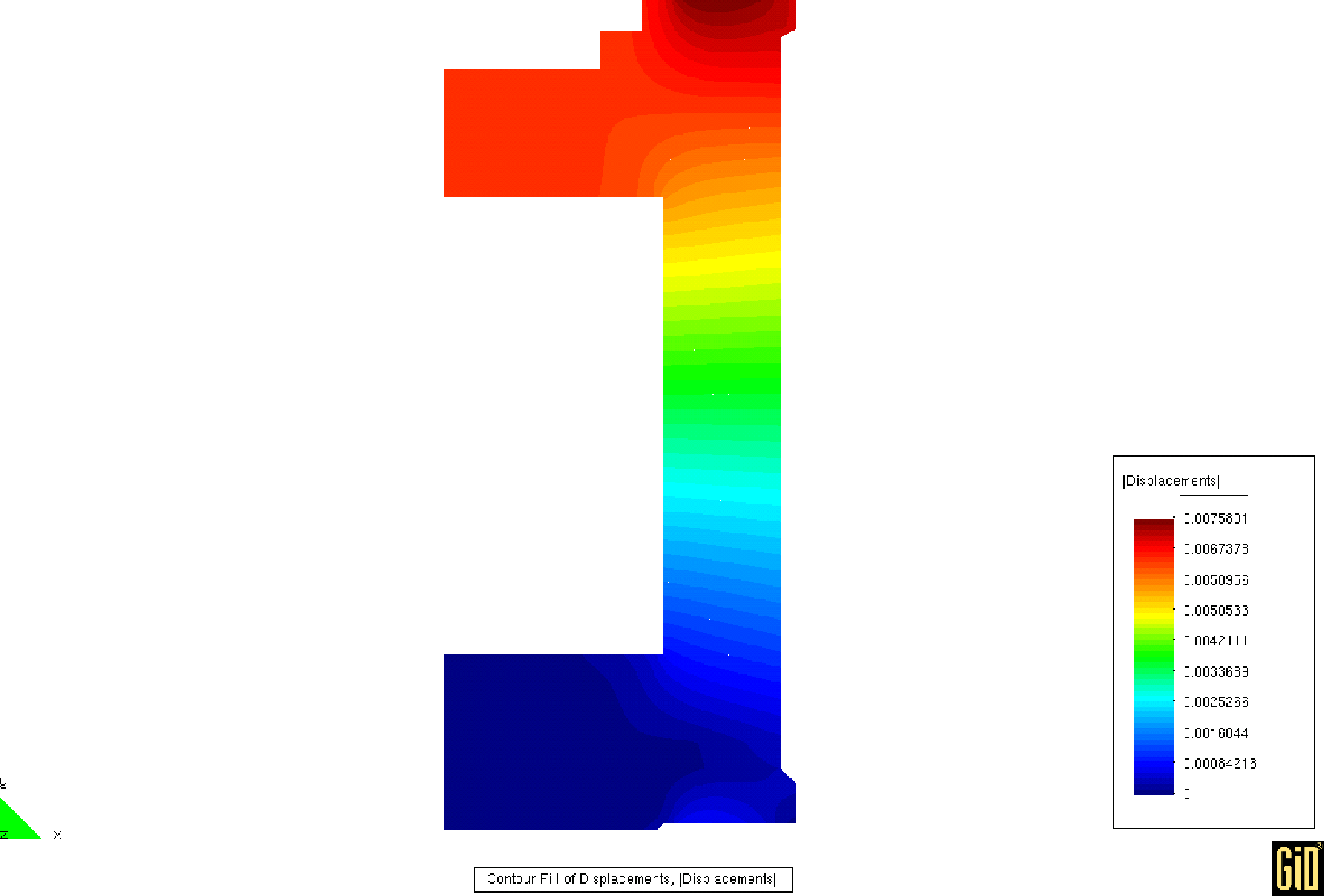
Figure 4 shows vertical displacement of selected point in time. There are several loading and unloading steps during the life of the vessel and they are clearly visible in the figure. Figure 5 shows deformation of the vessel caused by prestress only. This result was obtained separately from the hygro-thermo-mechanical analysis in order to cheque material model and prescribed load.
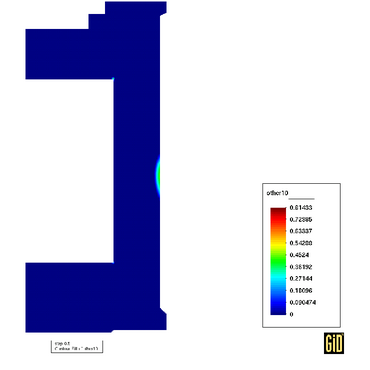
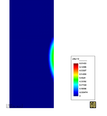
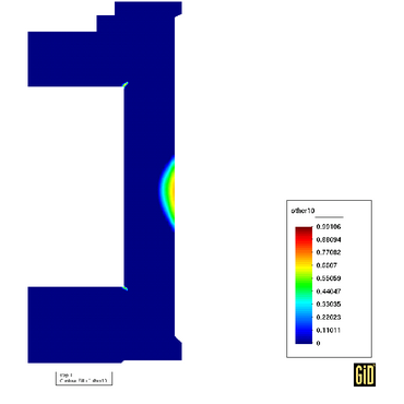
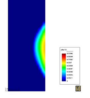
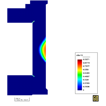
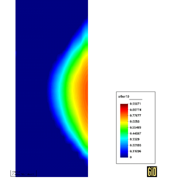
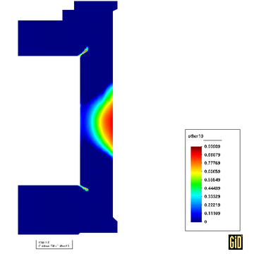
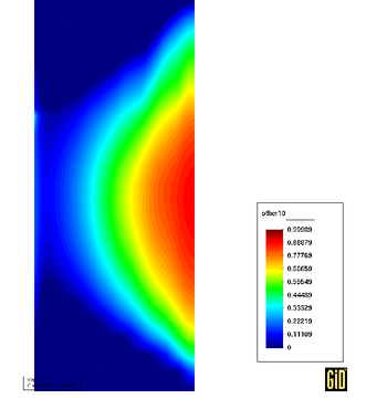
Limit state mechanical analyses were performed in order to estimate damage of the vessel after long period of service. Damage of the vessel was also computed for design failure which leads to growing inner pressure. Figure 9 shows distribution of damage for 1.5 multiple of standard inner pressure. Figure 10 shows distribution of damage for 2.8 multiple of standard inner pressure which causes destruction of the vessel.
Complex hygro-thermo-mechanical analyses and following limit state mechanical analyses were perfomed for exisiting nuclear vessel from prestressed cocncrete with inner steel liner. All analyses were computed by own software developed during MAECENAS project. Distribution of displacements, strains, stresses, pore pressures, temepratures and damage parameters were computed. Computationally very demanding analyses were parallelized with the help of the Schur complement method and homogeneous cluster with eight processors was utilized. Parallelization sped computation up because it reduced computational time for solution of system of algebraic equations as well as it reduced time for evaluation of complicated relationships in material models which were executed on thousands of integration points. Behaviour of the vessel during 33 years described by the hygro-thermo-mechanical analysis formulated as axisymmetric problem took only several hours on cluster of eight PC in comparison with several days on sigle-processor computer without parallelization.
[1] Z. Bittnar, J. Šejnoha Numerical Methods in Structural Mechanics ASCE Press, New York, USA, 1996
[2] M.A. Criesfield, Non-linear Finite Element Analysis of Solids and Structures John Wiley & Sons Ltd, Chichester, UK, 1991
[3] C. Farhat, F.X. Roux, Implicit parallel processing in structural mechanics, Comput. Mech. Adv., 2, 1-124, 1994.
[4] J. Kruis, Domain Decomposition Methods on Distrubuted Parallel Computers, Saxe-Coburg Publications, UK, in press, 2004.
[5] J. Kruis, T. Krejčí, Z. Bittnar, Numerical Solution of Coupled Problems In: Proceedings of The Ninth International Conference on Civil and Structural Engineering Computing [CD-ROM]. Stirling : Civil-Comp Press Ltd, 2003.
[6] R.W. Lewis, B.A. Schrefler, The Finite Element Method in the Static and Dynamic Deformation and Consolidation of Porous Media John Wiley & Sons, Chichester, England, 2000.
[7] M. Papadrakakis, Parallel Solution Methods in Computational Mechanics John Wiley & Sons Ltd, Chichester, UK, 1997.
[8] B. Smith, P. Bjørstad, W. Gropp, Domain Decomposition. Parallel Multilevel Methods for Elliptic Partial Differential Equations Cambridge University Press, Cambridge, UK, 1996.
[9] A. Toselli, O. Widlund, Domain Decomposition Methods - Algorithms and Theory Springer Series in Computational Mathematics, vol. 34. Springer-Verlag, Berlin, Germany, 2005.