Recently I have spent some time trying to understand the
differences among various models that deal with strain or
displacement discontinuities embedded into finite elements.
The table below shows why this has not been an easy task.
The number of embedded-crack formulations that emerged in
the literature during the past ten years is quite large
(not all of them are included in the table), and every author
has his (never her in this particular class of problems)
prefered notation and style of reasoning.
However, it seems that all the approaches can be classified
into three major groups that I tentatively call the
- statically optimal symmetric formulation (SOS),
- kinematically optimal symmetric formulation (KOS),
- statically and kinematically optimal nonsymmetric formulation (SKON).
|
formulation
|
authors
|
parent elements
|
discontinuity
|
material law
|
application
| SOS
| Belytschko et al. (1988) | quadrilaterals | weak | J2-plasticity | shear bands
|
| | Larsson and Runesson (1996) | CST | reg. strong | plasticity | mixed-mode fracture
|
| | Berends (1996) | CST | weak | smeared crack | cracking
|
| | Sluys (1997) | CST | weak | plasticity | shear bands
|
| KOS | Lotfi (1992), Lotfi and Shing (1995) | CST, Q4, QE5, QM6 | strong | cohesive crack | cracking of concrete
|
| SKON | Dvorkin et al. (1990) | Q4, QMITC | strong | cohesive crack | cracking of concrete |
| | Klisinski et al. (1991) | Q4 | strong | cohesive crack | cracking
|
| | Simo and Oliver (1994) | CST | reg. strong | damage, plasticity | shear bands
|
| | Oloffson et al. (1994) | CST | strong | plastic interface law | cracking
|
| | Oliver (1996) | CST | reg. strong | damage, plasticity | cracking, shear bands
Table 1: Overview of elements with embedded discontinuities
| |
The symmetric formulations (SOS and KOS) start from a natural
static or kinematic condition and then derive the other condition
from a variational principle. This is a consistent approach,
which however does not lead to a good performance of the element,
simply because the most natural static condition is not work-conjugate
with the most natural kinematic condition. It seems that the best
results can be obtained with the nonsymmetric formulation that
simply postulates each of the conditions independently, without regard
to variational consistency.
I have played with a constant-strain triangular element of this type,
trying to improve its performance on general unstructured meshes.
A
major problem of the standard formulations is that a displacement
discontinuity is introduced into the element right at the onset
of cracking. In a practical application, the mesh is usually not very fine
and not aligned with the actual direction of crack propagation, and
the direction of principal stress/strain often have considerable error.
Once the discontinuity is introduced, its direction remains fixed,
and if it was mispredicted it can happen that the crack does not
separate the nodes that should actually go apart. Spurious stresses
are generated in such element, and they can be released only by secondary
cracking. This complicates the numerical algorithm and artificially
increases energy dissipation.
 |
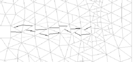
The band of cracking elements propagates from left to
right. In the rightmost cracking element, the embedded crack is
initiated in a completely wrong direction and it separates the nodes
incorrectly. This leads to severe stress locking.
|
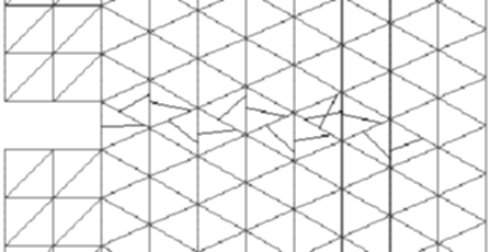 |
The band can propagate further only when a second
crack forms in the element where the direction was mispredicted.
The model must therefore allow for multiple embedded cracks in one
element. In more difficult simulations this can lead to problems
with convergence.
|
Figure 1: Secondary cracking due to mispredicted crack direction
A
possible remedy is offered by a combination of the embedded crack
approach with a smeared crack approach. A smeared rotating crack is
also often born in a partially incorrect direction but as the inelastic
strain increases the crack usually rotates closer to the ideal direction.
All we need for the present purpose is that it finds a position in which
it correctly separates the nodes that should end up on the opposite sides
of the resulting macroscopic crack. And this almost always happens,
because the way the nodes are trying to get apart has a strong influence
on the orientation of the inelastic strain. In the final stage of cracking
(formation of a stress-free crack) the smeared approach can lead to
spurious stress transfer (stress locking) but when we switch to the
embedded crack formulation at the right moment, the model should work
fine. My simulations, the details of which will be published later,
indicate that a model with transition from smeared to embedded crack
performs quite well and reduces or completely eliminates secondary
cracking.
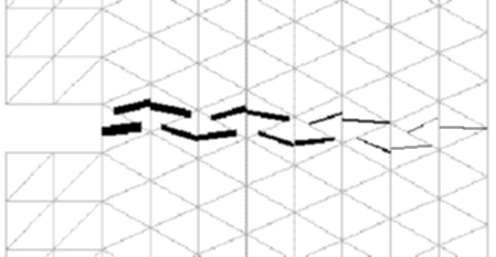 |
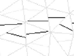
Cracks in the left part are already widely open and modeled
as discontinuities while cracks in the right part are still modeled by the
smeared approach (sorry that they are not plotted in a different color).
Each smeared crack can gradually adjust its direction before it turns into
an embedded discontinuity with a fixed direction, and so no secondary
cracking is necessary.
|
Figure 2: Crack pattern for combined model with transition from
smeared to embedded crack
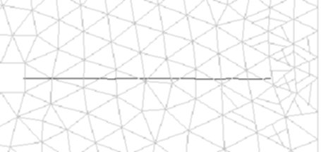
The
most promising results are obtained when the smeared part of the
model is formulated as nonlocal. This dramatically reduces mesh-induced
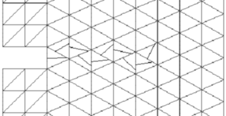
directional bias, as is documented by the following figure. All its parts
show in grey the triangular mesh and the cracks that are still in the
range modeled by the smeared approach. The dark lines correspond to cracks
that have already reached the range modeled by an embedded displacement
discontinuity. The smeared part is nonlocal in all examples below.
A detailed report on this research
as well as a compact conference paper
and a journal paper
are available upon request.
To the home page of Milan Jirásek.
EPFL /
13 March 1998 /
Milan.Jirasek@epfl.ch