SIFEL Home page
SIFEL - SImple Finite ELements
GENBRIDGE
Program creates input file into T3D mesh generator. The input file contains model of box bridge.
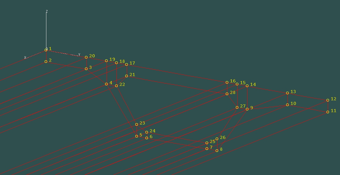
Fig. 1: Position of nodes in cross-section.
The program can be run by the following command:
./genbridge file_with_cross-sections output_file_for_T3d
file_with_crosssections consists cross-sections with coordinates of nodes. Each
cross-section has 28 nodes which are displayed on above figure. The coordinate system is also displayed on above
figure. There are six types of cross-sections:
- the cross-section at the end of the span
- the cross-section at the beginning of the stiffener
- the cross-section at the end of the stiffener
- the cross-section at the beginning of the span
- the cross-section in the middle of the span
- the cross-section in the middle of the span - beginning of the stiffener
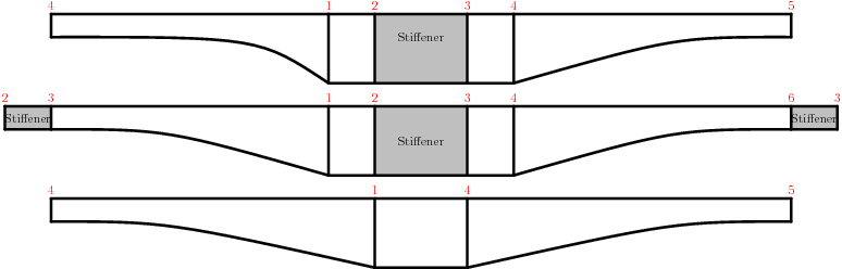
Fig. 2: Picture with type cross-sections.
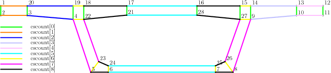
Fig. 3: Picture with cscount for discretisation of the cross-section.
Example of the file with cross-section without stiffeners:
bridgecrsc.in
Resulting generated file for T3D:
bridge.t3d.in
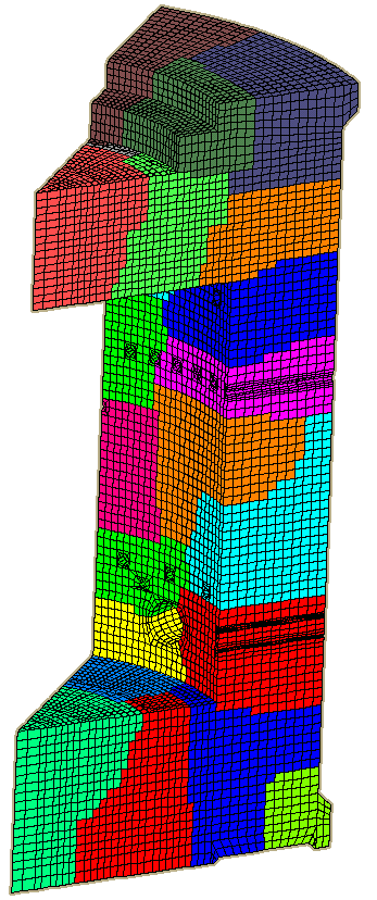
Image of T3D mesh generated with help of bridge.t3d.in:
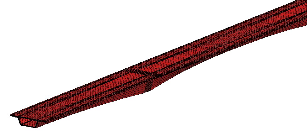
Fig. 3: Picture with cscount for discretisation of the cross-section.
Written by Jaroslav Broz 2010-11-12