SIFEL Home page
SIFEL - SImple Finite ELements
Preparation of input files
This section contains description of three basic approaches for the preparation of input files. By default, the plain input text file is required in modules. The second way - preferred - represents combination of several preprocessing tools for partial automatic generation of the input files. The last possibility is to use GiD environment where the GiD plugin module for SIFEL is loaded.1. Plain input files
All SIFEL computational modules require text input files which contain the setting of the problem solved.
The input files can be prepared with help of arbitrary text editor according to the following manuals
.in is used usually.
By default, the input files do not use keywords for the identification of input values, i.e. only numbers are given
and in certain cases, character strings. There is possible to add comments to the input file similarly to Linux shell
scripts. The comment starts with # character and finishes by the end given of line. The following
lines represents piece of nodal section of an input file where commented parts of lines are green:
4 # number of nodes

# node_id   x_coord   y_coord   z_coord   cross_sect_id   loc_coord_sys_id

1   0.0   0.0   0.0   0   0

2   2.0   0.0   0.0   0   0

3   3.0   4.0   0.0   0   0

4   5.0   4.0   0.0   0   0
Generally, the input file contains the following sections:
- Problem description - selection of problem type solved, selection of solver type, setup of solver, time stepping, backup of selected steps to harddisk, etc.
- Nodes - nodal coordinates, cross section types at nodes, nodal local coordinate system, etc.
- Dirichlet boundary conditions at nodes, coupling of DOFs
- Elements - element type, connectivity, cross section type, material type, etc.
- Materials - definition of material parameters used
- Cross sections - definition of cross section parameters
- Neumann and Newton boundary conditions - defined at nodes or elements
- Initial conditions - initial values given at nodes
- Output setup - selection of the results and format for their output
-kwd=n where n is number
which controls the keyword handling. More details can be obtained by the running of the given module without any
parameters which causes displaying of hints on the screen. The keywords allow for better checking of input file
format and in case of an error, the message is displayed including file position where the error was encountered.
2. Set of preprocessing tools
The second and preferred possibility of the input file preparation represents a set of tools involving automatic mesh generators, graphical mesh visualizer and editor and text command preprocessors. In the first step, the mesh is generated with help of automatic mesh generator. The mesh geometry is defined either in the text input file or by the command line options. The generators use so called property numbers to mark nodes and elements which are connected with some geometrical entity from the setting (e.g. vertex, edge, surface or volume). Additional property numbers can be added/extended with help of graphical MeshEditor tool. Having the FE mesh prepared, the input files for text preprocessors have to be created.
Mesh generators
FE mesh for the given geometry of the problem can be generated by the following generators whose output format
is accepted in text preprocessors:
- T3D mesh generator - very robust and fast generator
developed by D. Rypl, it can produce 2D or 3D meshes for almost arbitrary geometry. The generator needs text input
file whose format is described here
or there is short description in this link.
- Family of gensif{quad | quadq | hex | hexq | tetra | tria} generators - simple command line generators for the rectangular/brick
domains. They are placed in the folder
./PREP/SEQMESHGEN/of the SIFEL folder structure. The suffix at the end of generator name determines element type and shape function degree used. Domain dimensions and the mesh density can be specified in the form of command line parameters. These generators have to be compiled by the running of make command in the given folder (the GEFEL library is used and it must be compiled). If the generator is run without parameters it displays hints for the command line options. In the following example, a rectangular domain with dimensions 3.0 x 2.0 m placed in xy-plane will be generated with density 10 elements in x-direction and 5 elements in y-direction, edge property numbers are on.
gensifquad 3.0 2.0 10 5 1
- Bridgen - box girder bridge generator. It is placed in the folder
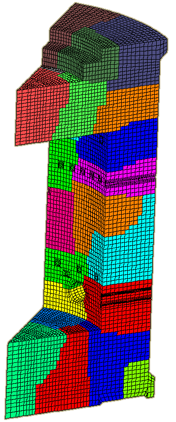
./PREP/BRIDGEN/of the SIFEL folder structure. It creates 3D structured mesh of box girder bridge from the linear hexahedron elements including stiffeners, variable wall thickness and height. The bridge geometry is given by set of characteristic cross section defined by several quadrilateral and triangle macro-elements. Bridgen was used for the mesh generation of real world problem of bridge in city of Mělník
MeshEditor
This graphical tool can load and display meshes in SIFEL and GiD formats. The T3D mesh format can be converted with help of Convertor into the SIFEL format. The property numbers of nodes and elements can be depicted and new property numbers can be added to the selected vertices, edges, surfaces or volume regions. For more details see section 3.5 of MeshEditor manual (in Czech).
Text preprocessors MECHPREP and TRANSPREP
There are preprocessors for MEFEL and TRFEL based on the text input file. The MEFEL preprocessor is called
MECHPREP and it can be found in ./MEFEL/PREP folder. The TRFEL preprocessor is called
TRANSPREP and it can be found in ./TRFEL/PREP folder. The text input files contain
the following sections:
- Input files - section which contains a list of external files used in the preprocessing such as mesh file, file with list of materials and their parameters, file with cross section types and their properties, etc.
- Problem description - the section has the same structure as the one in plain input files but keywords are switched on and used by default.<\li>
- Load case section - it defines the number of load cases and time functions used in the problem
- Output description (outdriver section) - the section has the same structure as the one in plain input files but keywords are switched on and used by default.
- Sections with nodal properties - these sections handles matters connected with nodes such as number of
degrees of freedom, local coordinate systems, nodal load or sources, Dirichlet boundary conditions, etc. The nodal
sections begins with keywords
begsec_nodXXXprand it finishes withendsec_nodXXXprwhereXXXstands for{vert | edg | surf | vol}entity identifiers (vertex, edge, surface, volume). Each section may contain commands that assign a nodal definition (load, source, ...) to the nodes which belong to the entity referred by the property number in the given command. For example the following line placed in the sectionbegsec_nodsurfprinstructs the preprocessor to assign 2 DOFs for each node which belongs to surface with property number 5:
begsec_nodsurfpr

.

.

ndofn 2 prop 5

.

endsec_nodsurfpr
- Sections with element properties - these sections handles matters connected with elements such as element
type, element materials or cords sections, element load or boundary conditions, etc. The element
sections begins with keywords
begsec_elemXXXprand it finishes withendsec_elemXXXprwhereXXXstands for{vert | edg | surf | vol}entity identifiers (vertex, edge, surface, volume). Each section may contain commands that assign an element definition (load, material, ...) to the nodes which belong to the entity referred by the property number in the given command. For example the following line placed in the sectionbegsec_elemvolprinstructs the preprocessor to assign elastic isotropic material (the second set of parameters in the material file) for each element which belongs to volume with property number 3:
begsec_elemvolpr

.

.

el_mat propid 3 num_mat 1 type elisomat type_id 2

.

endsec_elemvolpr
In the preprocessor files, the comment starts with # character and finishes by the end given of line
similarly to plain input file. Files with material and cross section parameters referred in the Input files
section have the same format as the corresponding sections in the plain input files (see
manual).
The MECHPREP can be invoked by the following commands:
mechprep file_m.pr file_m.in
file_m.pr is the input file for the preprocessor MECHPREP and file_m.in is
the name of resulting input file to MEFEL. Similarly, TRANSPREP can be invoked by the command:
transprep file_t.pr file_t.in
file_t.pr is the input file for the preprocessor TRANSPREP and file_m.in is
the name of resulting input file to TRFEL.
Examples, documentation
MECHPREP manual - Manual with more details about the MECHPREP preprocessor
Examples from MECHPREP manual - Zip archive with examples from the MECHPREP manual
Examples on web - Web benchmark examples of mesh generation, preprocessing of input file to MEFEL and TRFEL.
3. GiD preprocessor plugin
See the following link.